How Cyclones Work
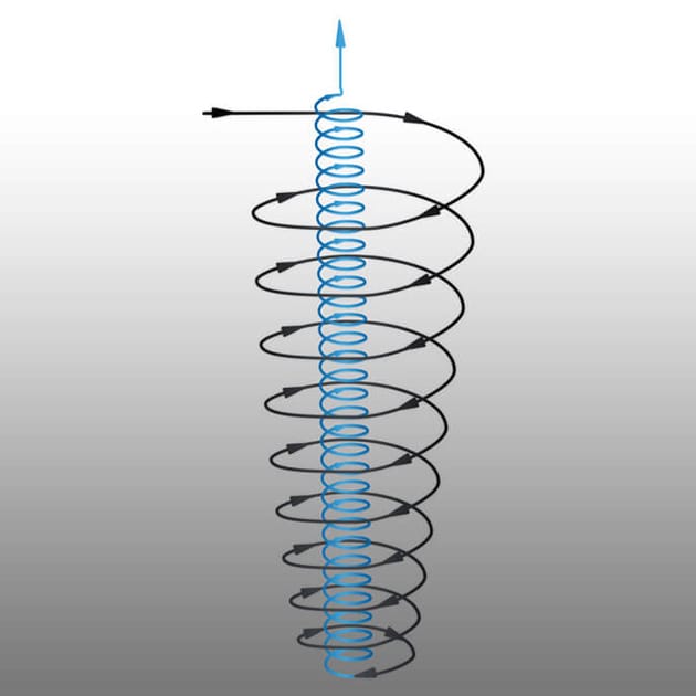
At their core, cyclones are simple machines, designed to separate solid particulate from a gas stream. They perform this task by taking advantage of the difference in density between the solid particulate and the gas stream that is conveying the particulate.
When a process gas containing particulate enters a cyclone, the shape of the cyclone causes the gas and particulate to start spinning downward. The centrifugal force of this column of spinning gas is referred to as a vortex. At the bottom of the cyclone, process gas is unable to continue moving further down due to the placement of a sealing device such as a rotary airlock.
As a result, the process gas turns on itself to begin moving upward toward the gas outlet at the top of the system. The particulate, with its greater momentum due to its higher mass, is unable to make the turn upward. This particulate continues into the dust receiver section of the equipment where it stays until it is removed.


High Efficiency Cyclones for Maximum Particle Capture
Our cyclones are built to handle demanding conditions, from high heat to ultra-fine particulates. Download the high efficiency cyclone pdf to see how they can be designed to approach filter-level performance, with flow mechanics, key specs, and adaptable configurations.
Have questions about integrating high efficiency cyclones into your process?
Our engineers are here to help you evaluate options and find the right fit. Let’s discuss your process needs.
Applications
Why Heumann Cyclones
Despite their operational simplicity, applying cyclone technology to various applications demands a significant level of expertise. While cyclones are straightforward devices to build and operate, their design demands a nuanced understanding of how different forces work to collect particles and keep them from becoming re-entrained in the gas stream.
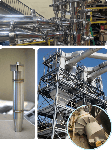
At Heumann Environmental, our engineers boast extensive experience in seamlessly integrating cyclones into a wide variety of applications. By harnessing our proprietary technologies to forecast performance, our team can draw on their expertise to provide precise performance predictions, enabling us to recommend the optimal cyclone design tailored to your specific requirements. This guarantees that our high-efficiency cyclones not only meet your performance criteria but achieves that goal at the most economical price point.
Features & Benefits
Reliable, Low-Maintenance Dust Collection, Even in the Toughest Environments

Cyclone Troubleshooting
The effectiveness of a cyclone often hinges not on the cyclone itself, but on how well it’s installed. While it’s easy to blame the equipment when performance falls short, installation errors or the omission of critical auxiliary components are more often to blame. Improper installation can severely undermine collection efficiency and trigger operational issues such as plugging, reentrainment, and erosion.
Below are some of the most commonly overlooked or mishandled aspects of cyclone installation—each with the potential to make or break system performance.

Gas leakage at the Discharge
Ensuring that the cyclone discharge is gas-tight is crucial. Even minimal gas leakage into the material discharge can suspend solids, promoting erosion, and destroying collection efficiency. While there’s a common misconception that cyclones operating at positive pressure don’t require airlocking, this is only true if:
Need Help? Download the Cyclone Troubleshooting Guide
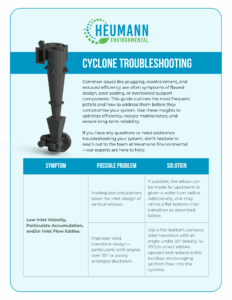
Cyclone installation issues can be complex, and symptoms often overlap. To help you pinpoint and resolve the root causes, we’ve created a detailed guide.
Download our full Cyclone Troubleshooting Guide to explore deeper diagnostics and practical solutions.
Reentrainment Risks Below Discharge
There is a misconception that once flow within the cyclone reverses that relatively ambient, calm conditions exist as the particles slowly fall towards the discharge. Tests have shown that a particulate sample can be completely fluidized at 12 discharge diameters below the cyclone discharge when operating at normal conditions. For all high-efficiency applications, some of the dust that’s supposed to be removed is reentrained into the air stream—reducing overall efficiency. Knowing this, it is critical that this is addressed proactively and additional equipment is properly installed. There are two routes that we recommend for addressing this:

Dust Receivers
Installing a dust receiver beneath the cyclone is essential to prevent the re-entrainment of previously collected particles. Disregarding this component based on misconceptions about particle behavior can lead to significant inefficiencies.
Tests have shown that without a dust receiver, re-entrainment can occur even at considerable distances below the discharge point. Dust receivers should ideally be at least two discharge diameters wide and three discharge diameters tall for optimal performance.

Vortex Breaker
Installing a vortex breaker can further minimize reentrainment by disrupting the cyclone’s vortex. These are suspended disks with supports that block the axis of the cyclone and allow the particulate to fall along the wall. By killing the vortex, re-entrainment below this point is eliminated.
However, careful consideration is required to ensure that the vortex breaker’s placement and design do not cause plugging or shorten the cyclone unit’s effective length. Additionally, the vortex breaker support must be able to handle the particulate abrasiveness and not erode or break.

Internal Obstructions
Any internal obstructions within the cyclone unit, whether part of the design or not, should be minimized to maintain smooth gas flow patterns. Even minor disturbances to gas flow patterns can result in notable increases in emissions.
Potential sources of obstruction range from instrumentation to poorly designed access doors, to uneven refractory installation. Access doors and instrumentation should be flush with the inner cyclone wall to avoid disruptions.

Flawed Inlet Design
Proper design of the inlet ductwork is critical to ensuring optimal cyclone performance. Factors such as the proximity of elbows to the cyclone, transition angles, and maintaining adequate conveying velocities must be carefully considered to minimize turbulence and prevent solids accumulation, which can lead to plugging and reduced efficiency.
When installing horizontal elbows within four duct diameters of the cyclone, they should align with the cyclone’s rotational direction to maintain uniform flow and minimize inlet disturbance.
While downward vertical elbows can be close-coupled to the cyclone inlet, upward vertical elbows require caution. These configurations often allow particulates to settle and accumulate within the inlet, leading to diminished efficiency and potential flow obstructions. Strategic elbow placement and thoughtful transition design can help prevent these issues and support consistent cyclone efficiency.
It’s important to note that these considerations are just a few among many critical requirements of cyclone installation. Every system has its own operating challenges. While these tips provide a strong foundation, true optimization comes from a deeper understanding of your system. Each cyclone application has its own operational dynamics—custom solutions deliver the best results.

Get a Clear Roadmap to System Improvement
Get expert eyes on your system. Our Cyclone Performance Evaluations offer data-backed diagnostics tailored to your process conditions—helping you prevent downtime, increase efficiency, and extend system life.

standard cyclone designs
Browse the full list of standard cyclone designs and models and download the technical drawings to see how its dimensions, features and tolerances will fit with your process.
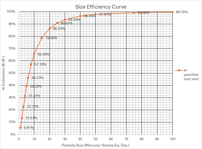
***Standard Cyclone predicted pressure drop and efficiency is based on the following design assumptions:
- Inlet Gas Composition = Ambient Air
- Inlet Air Temperature = 80°F
- Inlet Air Pressure = -4” In WG
- Particulate Specific Gravity = 1.0
- Particulate Loading = 5 Gr./C.F.
Deviations from these set conditions will impact cyclone performance. Contact us for performance estimates based on your specific process conditions.
| Airflow | Inches of Pressure Drop | Efficiency Tier | Download Options | |
|---|---|---|---|---|
| 100 | 5 inches | | | ||
| 110 | 5 inches | | | ||
| 120 | 5 inches | | | ||
| 130 | 5 inches | | | ||
| 140 | 5 inches | | | ||
| 150 | 5 inches | | | ||
| 160 | 5 inches | | | ||
| 170 | 5 inches | | | ||
| 180 | 5 inches | | | ||
| 200 | 5 inches | | | ||
| 225 | 5 inches | | | ||
| 250 | 5 inches | | | ||
| 275 | 5 inches | | | ||
| 300 | 5 inches | | | ||
| 325 | 5 inches | | | ||
| 350 | 5 inches | | | ||
| 375 | 5 inches | | | ||
| 400 | 5 inches | | | ||
| 425 | 5 inches | | | ||
| 450 | 5 inches | | | ||
| 475 | 5 inches | | | ||
| 500 | 5 inches | | | ||
| 550 | 5 inches | | | ||
| 600 | 5 inches | | | ||
| 650 | 5 inches | | | ||
| 700 | 5 inches | | | ||
| 750 | 5 inches | | | ||
| 800 | 5 inches | | | ||
| 850 | 5 inches | | | ||
| 900 | 5 inches | | | ||
| 950 | 5 inches | | | ||
| 1000 | 5 inches | | | ||
| 1100 | 5 inches | Standard | | | |
| 1200 | 5 inches | Standard | | | |
| 1300 | 5 inches | Standard | | | |
| 1400 | 5 inches | Standard | | | |
| 1500 | 5 inches | Standard | | | |
| 1600 | 5 inches | Standard | | | |
| 1800 | 5 inches | Standard | | | |
| 2000 | 5 inches | Standard | | | |
| 2200 | 5 inches | Standard | | | |
| 2400 | 5 inches | Standard | | | |
| 2600 | 5 inches | Standard | | | |
| 2800 | 5 inches | Standard | | | |
| 3000 | 5 inches | Standard | | | |
| 3250 | 5 inches | Standard | | | |
| 3500 | 5 inches | Standard | | | |
| 3750 | 5 inches | Standard | | | |
| 4000 | 5 inches | Standard | | | |
| 4250 | 5 inches | Standard | | | |
| Page 1 of 12 | ||||
Download Cyclone Resources Below

Trusted by process engineers and backed by decision-makers, HEC’s customizable cyclone solutions are engineered for performance and built for your process, delivering consistent particle separation, maximum system efficiency, and long-term reliability tailored to your operational needs.

Download our full Cyclone Troubleshooting Guide to explore diagnostics and practical solutions.

High Efficiency cyclones are built to handle demanding conditions, from high heat to ultra-fine particulates. See how they can be designed to approach filter-level performance, with flow mechanics, key specs, and adaptable configurations.